I. Introduction
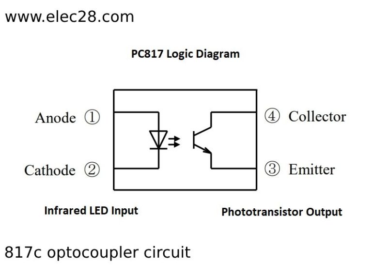
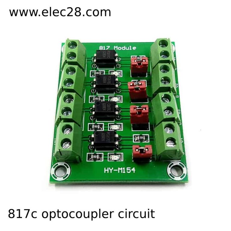
817C optrons are a crucial type of electronic component that are utilized in many circuits for voltage shifting and signal isolation. It is made up of a photodetector and an LED that are electrically isolated from one another yet housed in the same package. By ensuring that signals are transferred across several circuits without a direct electrical connection, this design guards against noise, ground loops, and voltage spikes.
II. Understanding the 817C Optocoupler
A. Overview of Optocoupler Functionality
Optical isolation is the foundation for the 817C optron’s operation. This indicates that light energy is produced when the input signal is applied to the LED component. A photodetector on the output side is then triggered by this light energy, producing an output signal in response. Complete electrical isolation, or the absence of any electrical connection between the input and the output, is an essential component of this procedure. The Optron 817C is the perfect choice for applications that need to be protected from high voltage, noise, and possible ground loops because of its isolation capacity.
B. Features and Specifications of the 817C Model
The 817C optron is a versatile part of electronics design because of its many functions and specs. Usually, it provides a high isolation voltage, guaranteeing reliable operation even in demanding applications. Furthermore, the Model 817C is well-known for having a low input current consumption, which makes it excellent for battery-powered devices and energy efficient. Furthermore, it frequently comes in a small, handy package that makes integration into different circuits simple. Because these properties allow them to create circuits that meet strict performance standards and are both dependable and efficient, engineers value them.
III. Design Considerations
A. Circuit Schematic and Components
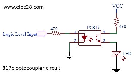
The schematic and the components involved must be carefully considered by engineers when developing an 817C optronic circuit. An LED is usually attached to the input side of the input signal source and a photodetector is connected to the load or receive circuit’s output side in a circuit layout. It is possible to add resistors and capacitors to the signal to guarantee correct signal conditioning and voltage level. Achieving the intended performance and guaranteeing the circuit’s overall reliability also depend heavily on the selection of suitable components.
B. Factors Influencing Circuit Design
The design of circuits utilizing the Optron 817C is influenced by various aspects. These variables include the necessary isolation voltage, the properties of the input and output signals, the operating environment, and any applicable regulations. To choose the best circuit topology, component values, and layout, engineers must carefully consider these aspects. In addition, to guarantee the best possible circuit performance and dependability in real-world applications, factors like power consumption, noise immunity, and signal integrity are crucial.
C. Tips for Optimizing Performance
Efficient 817C optron circuit performance necessitates meticulous attention to detail and application of best practices. By carefully choosing component values, optimizing layout, and reducing signal distortion and interference, engineers can increase performance. Furthermore, circuit performance and reliability can be greatly increased by employing strategies including insulating delicate components, using high-quality components, and implementing appropriate grounding procedures. Furthermore, comprehensive testing and validation protocols aid in detecting and resolving possible issues before to commissioning, guaranteeing that the circuit satisfies the desired specifications and functions dependably across a broad spectrum of operating circumstances.
IV. Application Scenarios
A. Examples of Common Uses for 817C Optocoupler Circuits
817C optrons find extensive application in a range of electronic circuits and systems. It is frequently used to increase safety and reliability in power circuits by forming an isolation between the high-voltage components and the control coil. Furthermore, it is frequently employed in communication networks to divide signals between various voltage domains, promoting compatibility and preventing harm to delicate parts. Furthermore, the optron 817C is employed in feedback isolation motor control systems, guaranteeing precise and steady motor performance in industrial and automotive applications.
B. Real-World Applications and Case Studies
The real world showcases the 817C optron’s adaptability through a multitude of applications. It is used, for instance, in industrial automation to isolate signals in control systems to shield PLCs and other equipment from noise and voltage spikes. It aids in the isolation of audio signals in audio equipment, lowering interference and enhancing signal clarity. Furthermore, the optron 817C guarantees patient safety in medical equipment by supplying isolation between various circuit components. The optron 817C’s dependability and effectiveness in practical applications are demonstrated by case studies that showcase its successful implementation in a variety of sectors.
V. Implementation Guide
A. Step-by-Step Instructions for Building 817C Optocoupler Circuits
Developing 817C optron circuits calls for a methodical approach. Assemble all required parts first, such as the 817C optron, resistors, capacitors, and any additional parts listed in the circuit design. Make sure that every component is positioned and oriented correctly by closely adhering to the circuit layout. The connections between the LED side of the optron, the input signal source, and the output load or receive circuit require close attention. To prevent any issues, double-check all of the solder joints and connections. Lastly, perform a comprehensive test to verify the circuit’s performance and make any required modifications.
B. Troubleshooting Tips and Common Pitfalls to Avoid
When deploying the optron 817C circuits, issues may still arise despite meticulous design and implementation. Inaccurate component values, bad connections, and layout issues that result in signal distortion or interference are common hazards. When debugging, begin by making sure that all voltage levels at crucial locations in the circuit are correct and that continuity is there. Inspect solder connections for indications of inadequate soldering or bridging. Additionally, consider how the environment—such as humidity and temperature—may impact the functionality of the circuit. Engineers can guarantee a successful and minimally disruptive implementation of the Optron 817C circuits by methodically identifying and resolving potential issues.
VI. Safety Precautions and Compliance
A. Importance of Adhering to Safety Standards
It is crucial to follow safety regulations when working with 817C optronic circuits. These regulations are intended to safeguard individuals and machinery against possible risks like electric shock, fire, and equipment damage. Engineers can reduce the chance of accidents and guarantee the secure operation of electronic systems by adhering to specified safety guidelines. When handling potentially dangerous components, safety precautions can include wearing personal protective equipment, grounding and protecting circuits, and installing adequate insulation.
B. Regulatory Considerations and Compliance Guidelines
When building and implementing 817C optronic circuits, engineers need to take regulatory requirements and compliance guidelines into account in addition to safety standards. Various regulatory bodies may set certain standards for electrical safety, electromagnetic compatibility, and environmental protection, depending on the application and industry. It is critical to verify that designs adhere to all legal criteria and to be knowledgeable about the pertinent rules. A company’s reputation may suffer, there may be fines and legal repercussions if regulatory standards are broken. Therefore, when developing and implementing 817C optron circuits, a detailed comprehension of and adherence to regulatory considerations are crucial.

VII. Conclusion
To sum up, engineers and amateurs alike must comprehend the design, use, and implementation of the 817C optron circuits. We have looked at the characteristics and functionality of the optron 817C, as well as several design factors and application cases. Engineers can successfully integrate 817C optrons into their projects by following the detailed instructions and abiding by safety standards and regulatory restrictions. Circuit dependability and safety are ensured by following safety regulations and using troubleshooting techniques.
Final Thoughts
The 817C optronic circuits’ versatility renders them important in a multitude of applications, spanning from consumer electronics to industrial automation. Their capacity to offer voltage shifting, signal conditioning, and electrical isolation enhances the dependability and performance of systems. The need for dependable and efficient circuits is increasing as technology develops, which highlights how crucial it is to comprehend and use parts like the optron 817C. These circuits can enhance the operation and security of electronic systems in a range of sectors when used properly and with the right understanding.


