NPN and PNP transistors are two types of bipolar junction transistors (BJTs) that are used for amplification or switching purposes. The primary difference between NPN and PNP transistors lies in how power is allocated to their terminal pins for them to provide amplification or switching. In this article, we will explore the differences between NPN and PNP transistors and their respective advantages and disadvantages, so you can make an informed decision on which one to use for your specific requirements and applications.
Catalog
The Introduction of The BJT Transistor
What are PNP and NPN transistors?
PNP and NPN transistors differ in what ways?
Transistor Effect
Switching using a Transistor
NPN transistor switching circuit
PNP transistor switching circuit
Applications of NPN and PNP transistors
Benefits of PNP and NPN Transistors
Frequenly asked Question
The Introduction of The BJT Transistor
A bipolar junction transistor (BJT) is a type of transistor used for amplification and/or switching purposes. It consists of three layers of semiconductor material, namely the emitter, base, and collector. The BJT operates by controlling the flow of current between the emitter and collector terminals, which is regulated by the current flowing into the base terminal.

There are two main types of BJT transistors: NPN (Negative-Positive-Negative) and PNP (Positive-Negative-Positive). The primary difference between NPN and PNP transistors lies in how power is allocated to their terminal pins for them to provide amplification or switching.
In this article, we will explore the differences between NPN and PNP transistors and their respective advantages and disadvantages, so you can make an informed decision on which one to use for your specific requirements and applications.
What are PNP and NPN transistors?
Transistors are created by mixing two different types of semiconductors: n-type and p-type. Electron donor atoms are carried by n-type semiconductors. The electron acceptor atoms are carried by p-type semiconductors (holes).
NPN transistor
NPN transistors are made of p-type semiconductor material with low doping levels. The emitter is doped with much higher donor impurities than the collector, while the collector is doped with much lower levels than the emitter.
The bias arrangement of NPN transistors is opposite to that of PNP transistors. The voltage has been reversed.
Electrons have a higher mobility than holes and are the main charge carriers of the NPN type. Therefore, the response time of NPN transistors is faster than that of PNP transistors. Therefore, NPN-type transistors are the most commonly used in high-frequency related devices, and they are simpler to manufacture than PNP-type transistors, making them the more commonly used of the two types.
PNP transistor
PNP transistors are made of n-type semiconductor material with low donor impurity doping concentration. The emitter is doped with a higher impurity concentration than the collector, and the collector is doped with a lower impurity concentration than the emitter.

NPN and PNP transistors
The BE junction is forward biased by applying a lower potential to the base, while the BC junction is reverse biased by applying a considerably lower voltage to the collector. PNP transistors can be used as switches or amplifiers in this form.
The holes, which make up the majority of the charge carriers in PNP transistors, have poor mobility. As a result, the frequency response rate is reduced and the current is limited.
PNP and NPN transistors behave similarly when used in circuits. However, the polarity of the voltage source connections and the direction of current flow are different. In most cases, NPN transistors can be replaced with PNP transistors and vice versa, but the supply polarity must be changed.
PNP And NPN transistors differ in what ways?
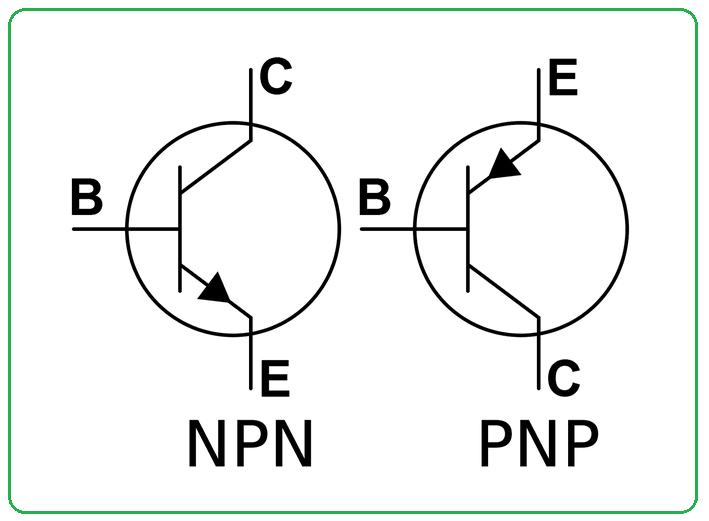
NPN and PNP transistors differ in their structure, operation, and applications. One of the significant differences is that in NPN transistors, when a positive supply is applied to the base, the current flows from the collector to the emitter, whereas in a PNP transistor, when a negative supply is applied to the base, the charge carriers flow from the emitter to the collector. . The following table shows a comparison of the two BJTs under different parameters.
| Parameter | NPN type | PNP type | |
|---|---|---|---|
| Structure | Two N-type layers separated by one P-type layer | Two P-type layers separated by one N-type layer | |
| Switching time | Lesser switching time hence faster switching | Higher switching time hence slower switching | |
| Direction of current | Collector to Emitter | Emitter to Collector | |
| Inside current | Develop because of the varying position of electrons | Originate because of the varying position of holes | |
| Majority carriers | Electrons are the majority carriers | Holes are the majority carriers | |
| Minority carriers | Holes are the minority carriers | Electrons are the minority carriers | |
| Turn-on instance | When electrons enter into the base | When holes enter the base | |
| Turn-off instance | Switches off by applying a low base voltage | Switches off by applying a positive base voltage |
NPN VS. PNP: Sign differences

NPN vs. PNP: Construction Differences
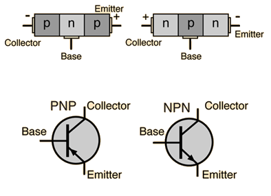
NPN-PNP-Building Diagram
NPN VS PNP: C-connection differences for Sensors
The main difference between NPN and PNP is how they are used in circuits. A sensor with an NPN output configuration acts as a sink output, while a sensor with a PNP output configuration acts as a source output.

Since many common industrial automation sensors operate at 24 Vdc, it is important to understand the two main variations of these solid-state devices.
Automation systems rely on discrete I/O signals, such as sensor inputs and field device outputs. These signals are used by various businesses and are powered by 120 volts. Use 24 Vdc is a safer and more common option, and many end users prefer devices with plugs and power cord connectors for easier installation and repair. It turns out that it takes a little forethought to secure a 24 Vdc sensor and PLC.The discrete input (DI) module is properly connected.
PNP and NPN are two types of 24 Vdc sensor. In order to work properly, they must be properly matched to the sink and pull DI modules. It’s not difficult, in fact, there is a somewhat traditional or at least typical method, as explained below.
Transistor Effect
Transistors are semiconductors that initialize micro-relays and are used in discrete device on/off sensor applications in transistor electronics. They amplify very small signals, such as the position sensing component of a proximity switch, in order to turn a larger signal on or off. This increased signal can be sent to a DI point, current, or any other device with the appropriate current rating. Transistors are divided into two types: PNP (source) and NPN (sink).
The letters “P” and “N” relate to the arrangement of semiconductor materials in PNP and NPN transistors. The connections between transistors are called base, collector and emitter. Fortunately, industrial automation requires an understanding of semiconductor physics.
Switching using a transistor
Transistors are commonly used in two types of applications: switching type operation and signal amplification. Solid-state switches can be created using transistors. The transistor acts as a closing switch when operating in the saturation region and as an off switch when operating in the cut-off region. Both PNP and NPN transistors can be used as switches. A transistor conducts current in the collector-emitter path only when a voltage is applied to the base. When no base voltage is present, the switch is closed. When the reference voltage is present, the switch opens.
In order for the transistor to operate in the cut-off region (open switching), both PN junctions are reverse biased, resulting in zero input and output current and a maximum voltage across the transistor. Therefore operates as an on switch. In order for the transistor to operate in the saturation region (open switching), both PN junctions are forward biased, resulting in maximum input and output current and minimum voltage across the transistor. Therefore operates as a closed switch.
NPN transistor switching circuit
To use an NPN transistor as a switch, the voltage applied to the base terminal is varied. When enough voltage is applied between the base and emitter (usually greater than 0.7V), the collector to emitter voltage is approximately equal to 0, which means the transistor acts as a short circuit or closed switch. Similarly, when no voltage or zero voltage is applied to the input, the transistor operates in the cutoff region and acts as an open circuit.
PNP transistor switching circuit
In a PNP type transistor, the base terminal is always negatively biased with respect to the emitter terminal, so current always flows from the base. When a voltage is applied at the base, the transistor acts as a closed switch and when zero voltage is applied at the base terminal, the transistor acts as an open switch.
Applications of NPN And PNP transistors
NPN transistor applications
While PNP and NPN sensors perform the same basic function, you may wonder why one is more popular than the other. There are certain differences, and NPN transistors are preferred in most circuit design applications. This is because the “N” substrate can transport positrons and holes much faster than the “P” substrate. This provides significant advantages for high-speed switching and amplifier circuit applications. In addition to this advantage, NPN transistors are easier to manufacture than PNP transistors and therefore cheaper to manufacture.
However, some circuits benefit from PNP-type transistors and are difficult, if not impossible, to implement without a second type of transistor. Class B amplifiers are one such application where a pair of matched PNP and NPN transistors work together to effectively amplify an oscillating signal. The second type of switching option is very useful when creating circuits.
PNP transistor applications
If you’re just starting out with these components, industrial sensors can throw a wrench into your knowledge if you’re not careful. As we all know, PNP and NPN sensors are equipped with positive and negative power leads, which then output a signal to indicate an “on” state. In the “on” state, the PNP sensor produces a positive signal to the industrial control input, while the NPN sensor produces a negative signal. If you learned to use sensors before learning about transistors, you might mistakenly believe that PNP transistors are controlled by positive voltages.
Benefits of PNP vs NPN Transistors
If true, a PNP sensor will connect +24 Vdc to the switch lead, while an NPN sensor will connect 0 Vdc to the switch lead.
If the cable is damaged, the signal may be grounded and damage the sensor. If the NPN cable is damaged, the signal may short to ground, resulting in a false signal, but no damage to the circuit.
The resulting logic is probably the most significant advantage of using PNP instead of NPN, as +24 Vdc=On=True is better than 0 Vdc=On=True
Easier for programmers and technicians to use and troubleshoot.
Frequenly asked Question
Q1How to choose a PNP or NPN sensor?
The type of circuit used in the system determines whether a PNP or NPN sensor is used. Most PLCs allow you to designate a card as PNP or NPN. Another point to remember is that NPN and PNP sensors should not be used together with PLC input cards.
Additionally, if you have a specific type of PLC input card, such as NPN or PNP, it is critical to select a matching sensor. For example, NPN sensors can be combined with NPN
Input card or “source” input card. However, PNP sensors cannot be used with NPN input cards.

NPN VS PNP BJT Transistor: Common Knowledge
NPN and PNP transistors are two types of bipolar junction…

test new
test new123456789
test project
test project123456789
Lorem ipsum dolor sit amet, consectetur adipiscing elit. Ut elit tellus, luctus nec ullamcorper mattis, pulvinar dapibus leo.


