
In the fast-paced realm of electronics, where speed, efficiency, and signal fidelity reign supreme, the intricate pathways on printed circuit boards (PCBs) serve a crucial function. Among these pathways, PCB transmission lines often go unnoticed, yet they are the silent champions, facilitating the dependable transmission of signals vital for modern electronic devices.
Comprehending and applying PCB transmission line theory holds immense importance in high-speed and high-frequency PCB designs. This knowledge ensures signal fidelity, minimizes electromagnetic interference, and upholds the overall performance of electronic devices.
What is PCB transmission line?
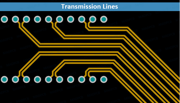
A PCB transmission line refers to a conductive pathway on a printed circuit board specifically designed to transmit electrical signals from one point to another. It’s engineered with specific characteristics to ensure the reliable and efficient transfer of signals, especially in high-speed and high-frequency applications.
These transmission lines consist of conductive traces typically etched onto the PCB’s surface, and they can take various forms, such as microstrips, striplines, or differential pairs, depending on the design requirements and signal properties.
The key characteristics and parameters of PCB transmission lines include impedance, propagation delay, signal attenuation, and signal integrity. Engineers meticulously design these transmission lines to match the required impedance levels and minimize signal distortion, reflections, and electromagnetic interference, ensuring the signals reach their destination accurately and without degradation.
PCB transmission lines play a crucial role in modern electronics, facilitating the communication and transfer of data between different components and ensuring the overall functionality and performance of electronic devices.
What is the purpose of transmission lines?
Transmission lines serve several critical purposes in electronic systems:
Signal Integrity: Their primary function is to maintain the integrity of electrical signals as they travel from one point to another on a printed circuit board (PCB) or within an electrical system. They help prevent signal degradation, distortion, and interference, ensuring that the signal arrives at its destination without significant loss or corruption.
Impedance Matching: Transmission lines are designed to match the impedance of the source (e.g., a microchip or a driver) to the load (e.g., another microchip or a receiver). Proper impedance matching minimizes signal reflections, optimizing the transfer of power and reducing signal distortions.
Reducing Electromagnetic Interference (EMI): Well-designed transmission lines help contain and reduce electromagnetic interference, preventing signals from interfering with adjacent circuits or systems and vice versa.
High-Speed Communication: In high-speed applications, transmission lines enable the transmission of signals at frequencies that require controlled and consistent signal propagation. They are crucial for maintaining signal integrity in systems with rapid data transfer rates.
Controlled Signal Propagation: Transmission lines control the speed and timing of signal propagation, ensuring that signals reach their destination synchronously and without distortion, especially in applications sensitive to timing, such as in telecommunications or digital systems.
Overall, transmission lines are fundamental components in electronic design, critical for ensuring reliable, high-quality signal transmission and maintaining the performance of electronic systems.
What are the types of transmission lines?
There are several types of transmission lines commonly used in electronic systems:
Microstrip Transmission Lines: These lines consist of a conductor (trace) on one layer of a PCB, separated by a dielectric material from a ground plane on the opposite side. They are widely used due to their ease of fabrication and versatility.
Stripline Transmission Lines: In stripline configurations, the conductor is sandwiched between two layers of dielectric material, with ground planes on both sides. This structure offers better shielding and reduced electromagnetic interference but can be more complex to manufacture.
Coplanar Waveguide (CPW): CPW transmission lines have the signal trace alongside ground traces on the same layer of a PCB, without a bottom ground plane. They offer good performance in high-frequency applications and are relatively straightforward to design.
Coaxial Cable: While not used on PCBs, coaxial cables are a type of transmission line consisting of a central conductor surrounded by a dielectric material and an outer conductor or shield. They are widely used for high-frequency applications and in communication systems due to their excellent shielding properties.
Differential Pairs: Differential pairs consist of two closely spaced traces carrying equal and opposite signals. They are employed to reduce electromagnetic interference and crosstalk, commonly used in high-speed digital signaling like USB, Ethernet, or HDMI interfaces.
These transmission line configurations have distinct advantages and are selected based on the specific requirements of the circuit or system, considering factors such as signal frequency, impedance matching, space constraints, and manufacturing considerations.
What is the difference between circuit and transmission line?
Circuits and transmission lines are both integral parts of electronic systems but serve different purposes and exhibit distinct characteristics:
Circuit:
Function: A circuit refers to a complete path formed by interconnected electronic components (such as resistors, capacitors, inductors, transistors, etc.) that enable the flow of electrical current to perform a specific function or task.
Characteristics: Circuits are designed for specific functions like amplification, filtering, signal processing, or logic operations. They manipulate signals or power in a controlled manner to achieve desired outcomes.
Behavior: In a circuit, the components interact primarily with the signal’s voltage and current characteristics. The interconnections between components are typically considered to have negligible effects on signal transmission, especially at lower frequencies.
Focus: The focus in circuits is on the behavior and function of individual components and their interactions within the circuit to achieve the desired electrical outcome.
Transmission Line:
Function: A transmission line refers to a structure specifically designed to transmit electrical signals or power from one point to another with minimal distortion or loss.
Characteristics: Transmission lines are engineered to control signal propagation, impedance, and other parameters to ensure the efficient and high-fidelity transmission of signals over distances or between components.
Behavior: In transmission lines, the interconnecting conductive pathways (such as traces on a PCB or coaxial cables) play a crucial role. They are designed to manage characteristics like impedance matching, signal reflections, and propagation delays, especially in high-speed or high-frequency applications.
Focus: The focus in transmission lines is on maintaining signal integrity, reducing losses, and controlling parameters like impedance to ensure effective signal transmission over distances or between components.
How are transmission lines connected?
Transmission lines can be connected in various ways based on the specific requirements of the electronic system. The method of connection depends on factors such as signal characteristics, impedance matching, and the type of transmission line used. Here are a few common methods of connecting transmission lines:
Series Connection: In series connection, the output of one transmission line connects directly to the input of another line. This method is simple but requires proper impedance matching between the lines to prevent signal reflections and loss.
Parallel Connection: Parallel connection involves connecting multiple transmission lines in parallel between two points. This setup can increase the total current-carrying capacity and reduce impedance in some scenarios.
T-Junction or Branch Connection: A T-junction or branch connection involves splitting a transmission line into two or more paths or merging multiple lines into a single path. Careful design is necessary to avoid impedance mismatches and signal reflections at the junction.
Connectors and Adapters: Connectors and adapters are often used to physically connect transmission lines, especially in situations where they need to interface with external devices or components. Proper connectors are crucial to maintaining signal integrity and impedance continuity.
Differential Pair Routing: In high-speed digital systems, differential pairs, which consist of two closely spaced traces carrying equal and opposite signals, are often routed together to minimize electromagnetic interference. They are designed to maintain consistent spacing and impedance along their length.
Why do transmission lines need high-voltage?
In certain contexts, transmission lines might operate at higher voltages due to various reasons:
Power Transmission: In electrical power transmission systems, higher voltages are used to reduce power losses during transmission. According to the laws of electricity (P = V^2 / R), for a given power (P), higher voltages (V) result in lower current (I) through the transmission lines, which, in turn, minimizes resistive losses (R), particularly over long distances.
Efficiency: High-voltage transmission is more efficient for transferring electrical energy across large distances. It enables the transmission of larger amounts of power with reduced losses compared to lower voltage systems.
Industry Standards: Some industries or applications might operate at higher voltages due to established standards, specific equipment requirements, or compatibility with existing infrastructure.
Specific Applications: Certain applications, such as high-power industrial machinery or specialized systems, might require higher voltages to achieve their operational requirements.
Conclusion
PCB transmission lines play a pivotal role in modern electronics, facilitating the smooth exchange of information within complex circuits. As technology progresses, the push for faster speeds, reduced latency, and heightened reliability will persist, sparking advancements in PCB transmission line design that shape the core of the electronic realm.
Mastering and leveraging the capabilities of these pathways will remain crucial in driving the forthcoming wave of innovations. This understanding ensures that the pulse of electronics maintains its rhythm with accuracy and effectiveness, steering the course for future developments.


