I. Introduction
A. Brief overview of Arduino R3
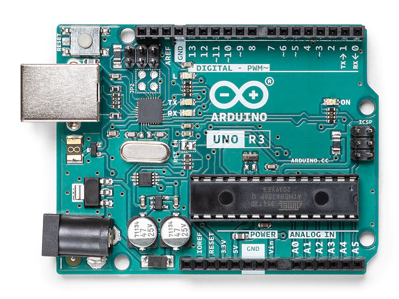
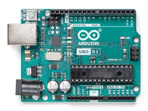
The Arduino R3 is a protean microcontroller board that has gained wide fashionability among potterers, preceptors, and professionals alike. Built upon the foundation of former Arduino models, the R3 offers enhanced features and capabilities, making it suitable for a wide range of systems. Its open-source nature and stoner-friendly development terrain have contributed to its wide relinquishment in the maker community.
B. Importance of the datasheet
The datasheet for the Arduino R3 serves as a comprehensive companion, detailing its specialized specifications, leg configurations, and electrical characteristics. It provides essential information for understanding the capabilities and limitations of the board, aiding in the design and implementation of systems. Whether you are a freshman or an educated inventor, pertaining to the datasheet is pivotal for maximizing the eventuality of the Arduino R3 and interacting with external factors and peripherals.
II. Technical Specifications
A. Microcontroller details
An essential part that drives the Arduino R3’s functionality is the ATmega328 microprocessor. The ATmega328 is a high-performance microcontroller with 32 KB of flash memory, 1 KB of EEPROM, and 2 KB of SRAM. It features an 8-bit AVR-RISC-based armature, immolation-effective prosecution of instructions, and robust performance for a variety of operations.
B. Operating voltage and current requirements
The Arduino R3 operates within a voltage range of 5 volts, making it compatible with a wide range of power sources generally used in electronic circuits. It generally consumes around 50 mA of current under normal operating conditions, although this value may vary depending on the specific peripherals and factors connected to the board. Understanding the voltage and current conditions is pivotal for choosing an applicable power force and ensuring stable operation of the Arduino R3.
C. Digital I/O pins and capabilities
The Arduino R3 features an aggregate of 14 digital I/O legs, each of which can be configured as either input or output. These legs are capable of uniting with external detectors, selectors, and other digital biases, allowing for protean commerce with the physical world. Also, several of these legs support palpitation-range modulation( PWM), enabling precise control of analog-like signals such as LED brilliance or motor speed.
D. Analog I/O legs and resolution
In addition to digital I/O legs, the Arduino R3 is equipped with 6 analog input legs, labeled A0 through A5. These legs enable the board to measure analog signals with a resolution of 10 bits, furnishing a range of values from 0 to 1023. This high resolution allows for accurate viewing of analog marvels such as temperature, light intensity, and voltage situations, expanding the capabilities of the Arduino R3 for a variety of operations.
III. Pinout Diagram
A. Detailed pinout layout
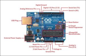
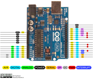
The pinout illustration of the Arduino R3 provides a visual representation of the physical layout of its legs and connectors. It illustrates the arrangement of digital and analog I/O legs, power-force connections, communication interfaces, and other supplementary factors on the board. This detailed layout serves as a precious reference for understanding the physical characteristics of the Arduino R3 and facilitates the process of connecting external factors and peripherals.
B. Functionality of each pin
Every pin on the Arduino R3 has a distinct purpose; these functions range from general-purpose digital and analog I/O to supplementary features and specialized communication interfaces. Designing and executing projects that make the most of the board’s possibilities requires an understanding of each pin’s operation. Whether it’s reading sensor data, driving actuators, or communicating with other devices, knowing the purpose of each pin enables precise control and interaction with the external environment.
C. Explanation of special-purpose pins
In addition to standard digital and analog I/O pins, the Arduino R3 includes several special-purpose pins that serve specific functions beyond basic input and output operations. These may include pins dedicated to power supply connections, reset functionality, programming interfaces, and onboard peripherals such as LEDs and buttons. Understanding the roles of these special-purpose pins is crucial for proper configuration and utilization of the Arduino R3 in various applications, ensuring compatibility and optimal performance.
IV. Electrical Characteristics
A. Voltage and current ratings
The Arduino R3 operates within a voltage range of 5V, with a recommended input voltage of 7–12V for optimal performance. It generally consumes around 50 mA of current during normal operation, although this can vary depending on the connected peripherals and the specific tasks being executed.
B. Input/output characteristics
The input and output characteristics of the Arduino R3 are essential for understanding its interactions with external biases and factors. The board features an aggregate of 14 digital I/O legs and 6 analog input legs, each with specific voltage situations and current capabilities. These characteristics determine the compatibility and functionality of peripherals connected to the board.
C. Power consumption details
When creating applications for the Arduino R3, power consumption is an important factor to take into account, especially for battery-powered or energy-efficient devices. By comprehending the specifics of power use, engineers may enhance the efficiency of their designs, prolonging battery life and lowering total energy consumption. Sleep modes, peripheral utilization, and processor demands are some of the factors that affect the board’s total power consumption.
D. Considering the environment
In bright operating circumstances, the dependability and longevity of the Arduino R3 are influenced by environmental factors. Similar elements that impact humidity, temperature, and electromagnetic interference can also have an impact on the stability and functionality of the board. By being fully aware of environmental concerns, formulators may design systems that function harmoniously and sustainably in a range of environmental conditions.
V. Application Examples
A. Sample projects and use cases
The Arduino R3 opens up a world of possibilities for creators, with countless sample projects and use cases available. From simple LED blinking exercises to complex home automation systems, the Arduino R3 can be employed in a diverse range of applications. Sample projects include weather stations, robot controllers, and interactive art installations.
B. Practical demonstrations of Arduino R3 capabilities
Practical demonstrations showcase the versatility and capabilities of the Arduino R3. For example, druggies can produce interactive widgets like stir-actuated lights or smartphone-controlled appliances. These demonstrations punctuate the ease of programming and rapid prototyping offered by the Arduino platform, empowering developers to bring their ideas to life quickly and efficiently.
VI.Conclusion
A. Summary of key points from the datasheet
The datasheet for the Arduino R3 encapsulates crucial technical information essential for understanding the board’s capabilities. From microcontroller details to pin configurations and electrical characteristics, it provides a comprehensive overview of the device. Referencing the datasheet ensures accurate implementation of projects and facilitates troubleshooting by offering insights into the board’s specifications.
B. Importance of referencing the datasheet for Arduino R3 projects
Consulting the datasheet is imperative for successful Arduino R3 projects. It serves as a reliable reference guide, aiding in the proper utilization of the board’s features and functionalities. By referencing the datasheet, developers can ensure compatibility with external components, optimize power consumption, and mitigate potential issues. Emphasizing the importance of the datasheet enhances project efficiency and reliability.

