I.Introduction
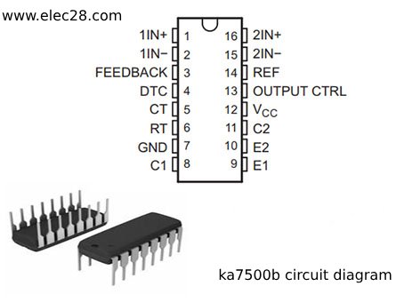
The KA7500B IC is a Pulse Width Modulation (PWM) controller commonly used in power supply circuits for various applications. It offers efficient control over the output voltage by adjusting the duty cycle of the PWM signal.
A. Brief overview of the KA7500B IC
The KA7500B is a versatile PWM controller designed to provide precise regulation in power supply circuits. Its architecture includes an error amplifier, PWM comparator, voltage feedback mechanism, and power stage. Its capacity to alter the duty cycle of the PWM signal enables steady and dependable output voltages over a wide variety of loads and input voltages.
B. Importance of understanding PWM control in power supply circuits
PWM control is essential in power force circuits because it allows for precise adaptation of affair voltages. The KA7500B adjusts the average voltage given to the cargo by changing the range of the beats in the PWM signal, icing steady performance under varying cargo conditions. Understanding PWM control is critical for developing power supplies with high efficiency, low noise, and low voltage ripple that match the severe requirements of today’s electronic gadgets.
II. Overview of the KA7500B Circuit Diagram
The KA7500B circuit diagram comprises several key components that work together to regulate the output voltage of a power supply efficiently. The following is an explanation of the key components:
Error amplifier:
To induce an error signal, the error amplifier compares the reference voltage( determined by external resistors) to the feedback voltage( commensurable to the affair voltage). This signal represents the difference between the asked and factual affair voltages, driving the PWM control circle.

PWM comparator:
The PWM comparator compares the error signal from the error amplifier to a triangle waveform produced by an internal oscillator. It uses the error signal to determine the range of the PWM signal, which controls the duty cycle and regulates the affair voltage.
Voltage feedback:
Voltage feedback is performed via a voltage divider network connected from the output to the IC’s feedback pin. This feedback mechanism keeps the output voltage steady by changing the PWM signal based on changes in the load or input voltage.
Power stage:
The power stage is made up of a power switch( similar as a MOSFET or bipolar transistor) and other factors like inductors and capacitors. It turns the PWM signal into a stable affair voltage by managing the current inflow to the cargo. The effectiveness and performance of the power stage greatly impact the overall performance of the power force.
III. Functionality of the KA7500B Circuit
A. Role of the error amplifier in generating the error signal
The error amplifier within the KA7500B IC is pivotal in comparing the reference voltage with the feedback voltage from the output. It calculates the difference between the desired and actual output voltages, generating an error signal. PWM control is essential in power force circuits because it allows for precise adaptation of affair voltages. The KA7500B adjusts the average voltage given to the cargo by changing the range of the beats in the PWM signal, icing steady performance under varying cargo conditions.
B. Operation of the PWM comparator in controlling duty cycle
The PWM comparator in the KA7500B IC compares the error signal from the error amplifier with a triangular waveform generated internally. This comparison determines the width of the PWM signal, controlling its duty cycle. The average voltage applied to the load is successfully regulated by the KA7500B by modulation of the PWM signal’s duty cycle. In order to attain and maintain the correct output voltage level, the PWM comparator is therefore essential for dynamically altering the pulse width, assuring stability and dependability in the power supply system.
C. Voltage feedback mechanism for regulation
Voltage feedback is integral to the KA7500B’s regulation mechanism. Through the use of a voltage divider network, the output voltage is sensed, and the error amplifier receives feedback. The feedback mechanism modifies the PWM signal in response to variations in the load or input voltage, guaranteeing that the output voltage stays constant within the intended range. By correcting for changes and disturbances to maintain constant performance under different operating conditions, this mechanism improves the power supply’s accuracy and stability.
D. Power stage and its impact on output voltage regulation
The power stage in the KA7500B circuit consists of the power switch (such as a MOSFET or bipolar transistor) and associated components like inductors and capacitors. This stage is responsible for converting the PWM signal into a stable output voltage. The output voltage regulation is greatly influenced by the power stage’s efficiency and performance since it directly regulates the current flow to the load. A well-thought-out power stage guarantees low voltage ripple, great efficiency, and dependable power supply operation, all of which enhance the overall longevity and performance of the system.

IV. Detailed Analysis of PWM Control
A. Understanding pulse width modulation (PWM)
By altering the duty cycle of a periodic waveform, an electronic circuit can control the quantum of power supplied to electrical bias through the use of palpitation range modulation, or PWM. PWM involves rapid switching of the signal between completely on and totally off states. It is possible to regulate the average power delivered to the load by changing the breadth of the on-time. This technique is frequently utilized in applications including motor control, dimming lighting, and voltage regulation because it enables effective power management without releasing excess energy as heat.
B. Importance of duty cycle in regulating output voltage
The duty cycle in PWM control represents the proportion of time during which the signal is in its high (on) state within one period. The effective voltage applied to the load can be accurately regulated by varying the duty cycle. For example, in a buck converter, the average output voltage lowers as the duty cycle is reduced, and the converse occurs when it is increased.
C. Factors influencing PWM control in the KA7500B circuit
Firstly, the reference voltage and feedback mechanism determine the desired output voltage level, which in turn affects the duty cycle required for regulation. Additionally, external components such as resistors and capacitors connected to the chip can alter its behavior, impacting the PWM waveform characteristics. Furthermore, the switching frequency and modulation scheme employed by the KA7500B chip also influence its performance and efficiency in regulating power delivery.

V. Applications and Considerations
A. Common applications of the KA7500B IC
The KA7500B IC finds widespread use in various applications, primarily in power supply circuits. It can be used as a pulse-width modulation (PWM) controller in switch-mode power supplies (SMPS), which is one typical application. By adjusting the PWM signal’s duty cycle, it controls the power supply’s output voltage. The KA7500B is also used in motor control circuits, battery chargers, voltage regulators, and LED drivers.
B. Design considerations for using the KA7500B in power supply circuits
Achieving the required performance and stability requires careful selection of all components, including external resistors, capacitors, and inductors. To guarantee precise voltage regulation and transient response, the feedback network needs to be carefully monitored. In addition, effective heat dissipation, reduced noise, and parasitic effects also depend on layout design. In order to prevent overvoltage, overcurrent, and overheating situations that could harm the integrated circuit and the surrounding components, sufficient protection circuitry must also be included. This will increase the system’s dependability and lifespan.
C. Tips for troubleshooting and optimizing performance
First, make sure the input and output voltages are within the designated range by checking them. Verify that all solder joints, connections, and component orientation are correct. To find any anomalies or irregularities, oscilloscope readings can be used to study the PWM waveform, duty cycle, and switching frequency. Hotspots indicating insufficient heat dissipation can be found using thermal imaging. Voltage regulation and transient responsiveness can be precisely tuned by adjusting feedback components like resistors and capacitors. In addition, consulting the datasheet for suggested operating conditions and application comments might offer important information for efficiently diagnosing and optimizing performance.
VI. Conclusion
Comprehending the circuit diagram of the KA7500B is crucial for attaining efficient PWM control in power supply designs. Through an understanding of the internal structure and functionality of integrated circuits (ICs), designers may enhance their performance, guarantee appropriate integration into the circuit, and resolve any potential problems. Knowing the circuit design makes it easier to choose and arrange external components correctly, enabling accurate voltage regulation and effective power management.


