I. Introduction
The ACS712, a linear current sensor that depends on the Hall effect, is well-known for its accuracy and ease of use. By detecting the current, it transforms the magnetic field created by a current passing through a nearby conductor into a corresponding voltage output. The ACS712 is widely used in various industries, including power management, industrial automation, and automotive, due to its sturdy design and broad current measuring range.
II. ACS712 pin configuration
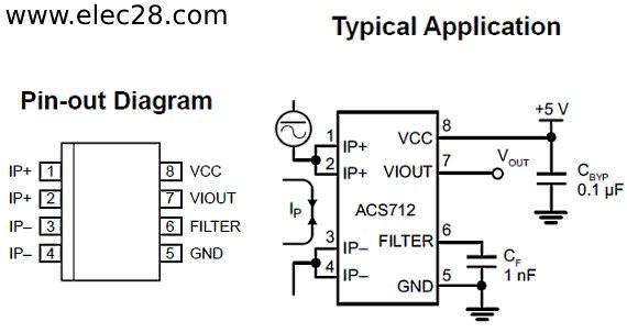
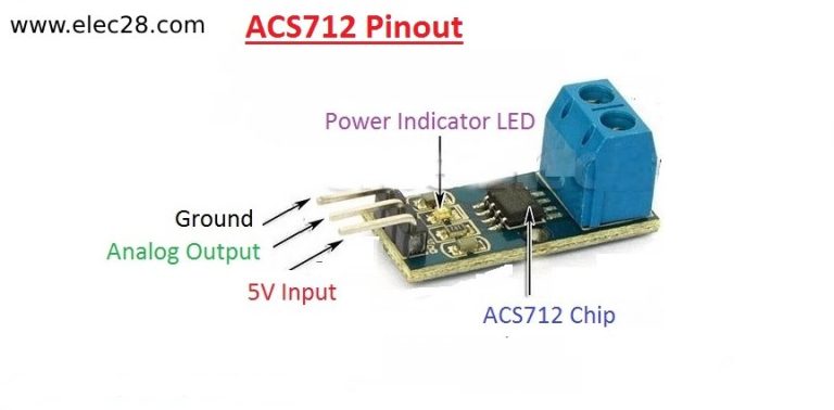
The ACS712 has three contacts: VCC, OUT and GND. These pins are usually clearly marked on the device, facilitating easy identification during circuit assembly and integration.
A. VCC (Voltage Supply Pin): The VCC contact is used to power the ACS712 sensor. A stable DC voltage within the specified operating range is required for proper operation. This pin is normally connected to the positive terminal of the power supply.
B. OUT (Output Pin): An analog voltage equivalent to the current passing through the sensor is provided by the ACS712’s OUT pin. To monitor and control current, this voltage signal can be directly interfaced to microcontrollers, analog-to-digital converters (ADCs), or other measuring devices.
C. GND (ground pin): The GND contact is the reference ground for the ACS712 sensor. It is connected to the negative terminal of the power supply and terminates the circuit, ensuring proper operation of the instrument.

III. Attachment diagram details
A. ACS712 pinout diagram
The ACS712 pinout diagram visually depicts its contact arrangement. It illustrates the relative locations of the VCC, OUT, and GND pins on the sensor package, helping users to correctly identify and connect them in their circuit designs. This diagram is often included in the data sheet provided by the manufacturer, providing a standard reference for users.
B. Marking and positioning of pins
Each ACS712 pin is typically marked for easy identification. The VCC pin may be marked with the letter “V” or “+”, the OUT pin with the letter “OUT” or simply “O”, and the GND pin with the letter “G” or “-“. In addition, the physical arrangement of the pins in the sensor package follows standardised practice, ensuring consistency between different ACS712 models and variants. Understanding the pin labeling and layout will help users to correctly connect the sensor to the circuit, minimizing the risk of wiring errors and ensuring reliable operation.

IV. Understanding Pin Connections
A. Interpreting the Pin Diagram
Pin assignments and their corresponding functions are explained in detail in the ACS712 pin diagram. Users may identify which pins are meant for the ground (GND), output signal (OUT), and power supply (VCC) by closely scrutinizing the diagram. To ensure proper performance and to link the sensor to other parts of the circuit, it is imperative that you comprehend this arrangement.

B. Making connections in the circuits
Once the pin diagram is understood, making connections in the circuits becomes easier. Using the pin assignments displayed in the diagram, users may determine which connections are suitable for power, signal output, and ground. It is important to take precautions to guarantee that connections are done safely and in accordance with the data sheet’s specifications. Correctly made connections are critical for reliable operation and accurate measurement of the circuit.
V. Practical applications
A. Examples of circuits using the ACS712
Many circuit designs use the ACS712 to monitor and measure current. It is frequently included into battery chargers, motor control circuits, power management systems, and renewable energy systems. For instance, in motor control applications, the ACS712 aids in controlling the motor’s current consumption to guarantee effective and secure functioning. Analogously, the sensor permits precise current monitoring in battery charging circuits, preventing overcharging and prolonging battery life.
B. Real world scenarios demonstrating the use of pins
In the real world, engineers and hobbyists use the ACS712 pin configuration to achieve specific features tailored to their applications. For example, in smart energy meters used in residential or industrial applications, the ACS712 output pin is connected to microcontrollers or data acquisition systems to accurately measure and monitor energy consumption. In the automotive industry, sensor pins facilitate the integration of current monitoring systems for battery management, vehicle diagnostics and security functions. These real-world applications underscore the importance of understanding and effectively using ACS712 pin connections for a variety of application requirements.

VI. Troubleshooting and tips
A. Common problems with pin connections
Incorrect pin connections are a frequent issue that users may run into, which can lead to erroneous results or sensor problems. Erroneous wiring or a misreading of the connection schematic may be the cause of this. Furthermore, unstable signals or sporadic performance may be brought on by shoddy soldering or loose connections. Identifying and correcting these problems is essential to ensure reliable operation.
B. Tips for accurate pin operation and troubleshooting
To ensure accurate pin operation and troubleshooting, it is critical to consult the data sheet and contact diagram provided by the manufacturer. Double-checking connections and checking pin assignment will help to avoid potential errors. In addition, the use of proper wiring techniques (e.g. shielding of sensitive signal lines and minimizing interference) can increase sensor performance and reliability. Regular calibration and testing of the transducer under different operating conditions can also help to quickly identify and resolve problems. By following these tips, users can optimize ACS712 performance and troubleshoot efficiently.
VII. Conclusion
In conclusion, an understanding of the ACS712 pin diagram is essential to realize the full potential of this current sensor. Throughout this guide, we have explored pin configurations, details, practical applications, troubleshooting techniques, and tips for accurate operation. Mastery of the ACS712 contact diagram will enable engineers and hobbyists to design accurate flow measurement systems for a variety of applications.
VIII. Final thoughts
Accurate current sensing solutions are becoming more and more necessary as technology develops in a number of areas, such as industrial automation, renewable energy, and the automotive sector. Mastery of the ACS712 pin diagram opens up opportunities to explore innovative applications and develop sensor integration and circuit design skills. In addition, ongoing research and development in current sensor technologies offers exciting opportunities for further learning and specialisation in this field. By staying up to date and continuously improving their knowledge, enthusiasts can stay at the forefront of emerging trends and contribute to the development of current measurement solutions.


