I. Introduction
The STM32F103C8T6 microcontroller is part of the STM32 family developed by STMicroelectronics. It features a high- performance ARM Cortex- M3 core, offering robust processing capabilities suitable for a wide range of bedded operations. With its rich set of peripherals and expansive connectivity options, the STM32F103C8T6 is extensively used in colorful diligence, including automotive, artificial robotization, and consumer electronics.
II. Pinout Configuration
A. Detailed Breakdown of Pin Functions
The pinout configuration of the STM32F103C8T6 microcontroller entails a comprehensive breakdown of the functions assigned to each leg. This breakdown generally includes details similar as GPIO( General Purpose Input/ Affair), analog input, communication interfaces( UART, SPI, I2C), power force legs, and other technical functions.
B. Identification of Essential Pins and Their Roles
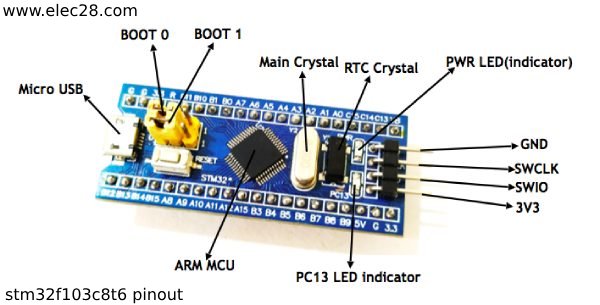
Among the multitude of legs available on the STM32F103C8T6 microcontroller, certain legs hold essential places critical for colorful functionalities. These essential legs may include power force legs, ground legs, reset legs, timepiece legs, and legs dedicated to programming and debugging interfaces( similar as SWD and JTAG). also, understanding their places aids in troubleshooting and debugging during the development phase. By pinpointing these crucial legs and comprehending their significance, inventors can ensure the trustability and robustness of their embedded systems built around the STM32F103C8T6 microcontroller.
III. Pinout Diagram
A. Visual Representation of Pin Assignments
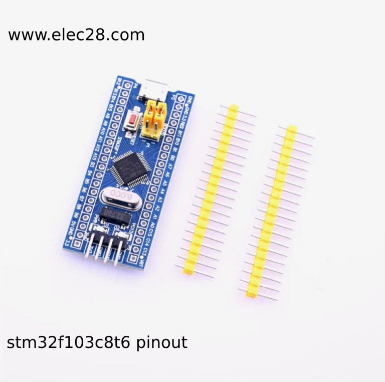
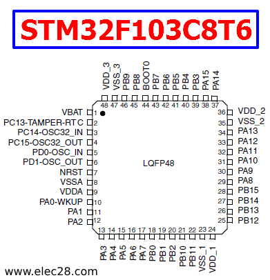
A pinout illustration provides a graphical representation of the leg assignments on the STM32F103C8T6 microcontroller. It illustrates the physical arrangement of legs and their corresponding functions in a clear and terse manner. generally, pinout plates include information similar as leg figures, names, and functions. This visual representation allows inventors to snappily reference and identify the position and purpose of each leg, facilitating effective circuit design and tackle integration. also, the pinout illustration serves as a precious reference tool during the development process, aiding in troubleshooting and verifying correct connections.
B. Explanation of Pin Labeling and Layout
To guarantee thickness and clarity, the pinout illustration’s labeling and arrangement adhere to a set standard. To indicate its purpose and connectivity, each pin is labeled with a unique identity, which is often a string of alphanumeric characters. The pin configuration in the figure corresponds to how they are physically arranged on the microcontroller chip, where they are arranged logically and methodically for convenience of reference. To further improve reading, pin labeling may also incorporate color coding or other visual clues. Comprehending the pin arrangement and labeling in the pinout picture is crucial for accurately analyzing the data displayed and efficiently employing the STM32F103C8T6 microcontroller in embedded system architectures.
IV. Pin Functions and Usage
A. Description of GPIO Pins and Their Usage
GPIO( General Purpose Input/ Affair) pins are protean pins on the STM32F103C8T6 microcontroller that can be configured as either inputs or labors. These pins play a pivotal part in uniting with external bias similar as detectors, LEDs, switches, and other digital factors. GPIO pins can be used for colorful purposes, including reading digital inputs, driving digital labors, generating interrupts, and enforcing communication protocols similar as SPI or I2C.
B. Special Function Pins and Their Applications
In addition to GPIO pins, the STM32F103C8T6 microcontroller features special function pins devoted to specific tasks or functionalities. These special function pins include power force pins, ground pins, reset pins, timepiece pins, and pins for programming and debugging interfaces similar as SWD( periodical line Debug) and JTAG( Joint Test Action Group). Each of these pins serves a critical part in the operation and functionality of the microcontroller within a system. Power force pins give the necessary voltage and current to power the device, while ground pins insure proper electrical grounding. Reset pins allow for resetting the microcontroller, while timepiece pins give timing signals for coetaneous operations. Programming and debugging interfaces enable firmware development, law debugging, and in- circuit programming.
V. Practical Examples
A. Circuit Diagrams Illustrating Pin Connections
Circuit diagrams serve as inestimable tools for illustrating how pins on the STM32F103C8T6 microcontroller are connected within a system. These diagrams give a visual representation of the electrical connections between the microcontroller and other factors or peripherals. They detail the pin assignments, signal paths, and interconnections necessary for proper functionality. also, circuit diagrams aid in troubleshooting and debugging by allowing masterminds to visually check and corroborate the integrity of the connections within the system.
B. Real-World Applications Showcasing Pin Usage
Real- world operations offer palpable exemplifications of how pins on the STM32F103C8T6 microcontroller are employed in practical scripts. These operations gauge colorful disciplines, including artificial robotization, consumer electronics, automotive systems, and more. For case, GPIO pins may be used to affiliate with detectors for environmental monitoring, control selectors in robotics operations, or drive LEDs for status suggestion. Special function pins similar as UART, SPI, or I2C interfaces grease communication with supplemental bias like displays, detectors, or wireless modules.
VI. Tips and Best Practices
A. Recommendations for Optimal Pin Configuration
Optimal pin configuration is essential for maximizing the performance and reliability of the STM32F103C8T6 microcontroller in embedded applications. One recommendation is to carefully plan and document the pin assignments before hardware implementation. This involves allocating pins for specific functions based on their requirements and ensuring that conflicting functionalities are avoided. Additionally, it’s advisable to leverage the microcontroller’s pin multiplexing capabilities to maximize pin utility and minimize resource wastage. likewise, clinging to recommended operating conditions, similar as voltage situations and current limitations, helps help damage to the microcontroller and ensures long- term trustability.
B. Common Pitfalls to Avoid When Working with Pinout
When working with pinouts, several common pitfalls can hinder successful hardware integration and functionality. One common pitfall is improper signal routing, which can lead to signal integrity issues, noise interference, or cross-talk between adjacent pins. To avoid this, engineers should carefully design PCB layouts to minimize signal routing length and optimize signal paths. Another pitfall is overlooking pin configuration settings in firmware, leading to misconfigured peripheral interfaces or incorrect pin functionality. Thoroughly reviewing datasheets, reference manuals, and application notes can help mitigate these pitfalls and ensure proper pin configuration for desired functionality. Additionally, diligent testing and validation of hardware and firmware implementations are crucial for identifying and addressing any pin-related issues early in the development process.
VII. Conclusion
As technology evolves, so do the capabilities and operations of microcontrollers like the STM32F103C8T6. Continued disquisition and literacy about its pinout, along with advancements in bedded systems design, offer instigative openings for invention and development. masterminds and suckers are encouraged to claw deeper into the complications of leg configuration, interface design, and optimization ways to unleash the full eventuality of the STM32F103C8T6 microcontroller.


