I. Introduction
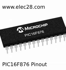
The PIC16F876 microcontroller from Microchip Technology combines affordability, functionality, and performance in a way that makes it appropriate for a broad range of embedded systems and applications, from basic to sophisticated.
A. Brief overview of PIC16F876 microcontroller
A potent 8-bit RISC (Reduced Instruction Set Computer) processor that can quickly execute instructions is included within the PIC16F876. It can code more effectively and use resources more efficiently because of its reduced instruction set. Microcontrollers come with built-in peripherals that allow developers to add a wide range of functionality to their projects. Examples of these peripherals include timers, ADCs (analogue-to-digital converters), and USARTs (universal synchronous/asynchronous receiver/transmitters).
B. Importance of understanding pinout for effective usage
The pin layout describes each pin’s function and actual location within the microcontroller. Once developers have a thorough grasp of the pin arrangement, they can configure I/O (input/output) ports, connect external components, and communicate with other devices.
II. Understanding the PIC16F876 Pinout
A. Pin configuration and functionalities
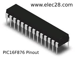
Three primary types of sockets are available for the PIC16F876 microcontroller: special function pins, I/O pins, and power pins. These are essential to its correct functioning.
Power supply pins: These pins are essential for giving the microcontroller the ground and voltage connections it needs. To guarantee the device operates steadily, they usually contain VDD (positive supply voltage) and VSS (ground) pins.
I/O pins: The interface between the microcontroller and external parts or peripherals is provided via the I/O pins. 3. Pins for I/O.
Special function pins: Special function pins: These pins have special functions that go beyond the basic I/O operation. These may include programming/debugging pins, oscillator connections and reset pins.
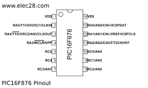
B. Pinout diagram analysis
Finding Crucial Pins: Developers can easily find important pins, such as the clock signal oscillator, output pins and power supply pins.
PIC16F876 Features and Performance The PIC16F876 has pins for digital inputs and outputs, analogue inputs and outputs, and communication interfaces, each with its own purpose. In addition, the pin layout diagram usually includes information on pin multiplexing, alternative functions and pin characteristics to facilitate correct configuration and use.
III. Exploring Connections and Applications
A. GPIO applications and configurations
The PIC16F876 microcontroller’s general purpose input/output (GPIO) pins carry out a number of tasks to communicate with an extensive array of external parts and peripherals. For a range of purposes, these pins can be set up as inputs or outputs.
B. Interface connections (e.g., LCD, sensors)
It is possible to link LCD screens, actuators, sensors, and other external devices to the PIC16F876 microcontroller. Generally speaking, the right pin of the external device needs to be linked to the right GPIO pin in order to make an interface connection.
C. Communication protocols (e.g., UART, SPI)
The PIC16F876 microcontroller can connect with other microcontrollers, displays, and sensors with ease thanks to these protocols.
D. Analog input/output configurations
Sensor analogue signals can be processed and converted into digital values using Analogue-to-Digital Converter (ADC) modules and a microcontroller. The microcontroller can provide analogue output signals using a digital-to-analog converter (DAC) module, which can then be utilized to operate analog devices like amplifiers or motors. You must choose the correct ADC channel, modify the sampling rate, resolution, and reference voltage, as well as the output voltage and DAC waveform, in order to create the analogue inputs and outputs.
IV. Practical Examples and Implementation Tips
A. Sample circuit designs
The example circuit designs provide a practical overview of the application of the PIC16F876 microcontroller in real projects. These designs typically include schematics, component lists and functional descriptions.
B. Tips for efficient pin utilization
Pin optimization techniques include maximizing pin counts to accomplish many tasks, allocating pins in order of importance and frequency of usage, and optimizing I/O setups to minimize power consumption. The effectiveness and adaptability of pin use can also be increased by employing strategies like interrupt-driven I/O and pin allocation systems.
C. Common pitfalls and troubleshooting techniques
wrong pin assignments, insufficient power supplies or disconnections, wrong clock configurations, and software defects are the most frequent issues. A range of techniques can be employed by developers to debug these issues, including the use of tools like logic analyzers and in-chain simulators, thorough testing of individual parts and connections, and consultation of pertinent web and manual resources.
V. Conclusion
A. Summary of key points
In this article, we looked at the PIC16F876 microcontroller, including its pinout, functions, and practical applications. We began by offering a detailed review of the microcontroller’s characteristics and capabilities. We then looked at the pin configuration and functionality, highlighting the need of power supply, I/O, and special function pins. Furthermore, we analyzed the pinout diagram to identify key pins and understand their functions and capabilities. Moving forward, we explored various connections and applications, including GPIO interfacing, interface connections, communication protocols, and analog input/output configurations. Finally, we discussed practical examples, implementation tips, common pitfalls, and troubleshooting techniques to aid developers in effectively utilizing the PIC16F876 microcontroller.
B. Importance of understanding PIC16F876 pinout for successful projects
Understanding the pinout of the PIC16F876 microcontroller is critical to the success of projects employing it. The pinout diagram acts as a road map, directing developers through proper pin setup, interface connections, and peripheral utilization. By thoroughly understanding the pinout, developers may avoid frequent mistakes, improve pin consumption, and ensure that their applications run reliably. Furthermore, a solid understanding of the pinout allows fast troubleshooting and debugging, allowing engineers to quickly diagnose and resolve issues as they emerge. Finally, knowing the PIC16F876 pinout enables developers to maximize the microcontroller’s capabilities, resulting in the effective implementation of a wide range of embedded systems and electrical projects.


