Although switching reluctance motors, or SRMs, are not a novel technology, their commercial versions have just recently been released. When compared to other types of motors, the designers of this one claimed to offer higher efficiency, greater dependability, a lower cost, and superior performance. The year 1838 marked the recognition of the SRM concept. A switched reluctance motor’s primary advantages are its dependability, improved performance, high motor-drive efficiency, low total system cost, etc. An overview of the switching reluctance motor is included in this article.
What is a Switched Reluctance Motor?
Reluctance torque powers an electric motor such as an SRM (switched reluctance motor). In contrast to typical brushed DC motor types, power can be sent to the stator’s windings rather than the rotor. This motor is also known as a VRM (Variable Reluctance Motor). The switching inverter is used by this motor to improve its performance. This motor’s control characteristics are identical to those of electronically commutated dc motors. These motors are useful in situations where weight to horsepower (hp) ratio is important.
This motor’s mechanical construction is made simpler to prevent current from flowing toward a rotating part, but it is made more complex since power must be transmitted to the various windings via the use of a switching mechanism. One can also utilize this mechanical design for a generator. To synchronize the current flow during the rotation, the load can be redirected toward the coils in the sequence. Because the armature of these generators is composed of a single piece of magnetizable material, such as a slotted cylinder, they are also capable of operating at higher speeds than other traditional motor types.

Working Principle of the Switched Reluctance Motor
The switched reluctance motor operates on the basis of changeable reluctance, which implies that its rotor is continuously trying to align itself through the reluctance lane with the lowest resistance.
The circuit of power electronics switching can be used to create a rotating magnetic field. In this case, the air gap may be the primary determinant of the magnetic circuit’s resistance. Thus, we can adjust the reluctance of this motor by altering the air gap between the rotor and stator.
Reluctance in this context is defined as opposition to the magnetic flux. Reluctance in electrical circuits is the result of the magnetic circuit and resistance working together.
Switched Reluctance Motor Construction
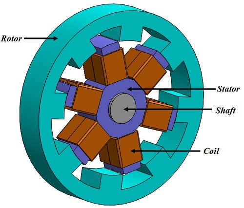
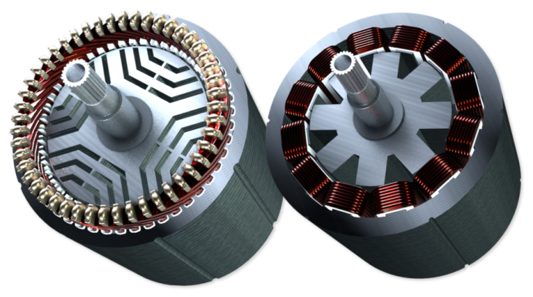
The switching reluctance motor’s construction is depicted below. This motor has four rotor poles and six stator poles. In order to design the stator, silicon steel stampings inside predicted poles can be used. Either an odd or an even number of poles make up the stator. The majority of electric motors use a stator with an even number of poles that are equipped with field coils.
The field coils will be connected in series when the poles are opposite. Their phase windings, or magnetomotive forces, are hence additive. Phase windings might be a single coil or a group of coils. Every winding has the option to be linked to the motor terminal, and these are correctly connected to the o/p terminals of a power semiconductor switching circuit. This takes a DC supply as its input.
Si steel stampings can be used to design the rotor through externally projected poles. When compared to the stator poles, the rotor poles differ. Most modern motors have four rotor poles; in certain cases, six, depending on how many stator poles there are—for example, six or eight. The position sensor is mounted on the rotor’s shaft. Thus, the signals obtained from this sensor are primarily responsible for controlling the operation of numerous devices in the power semiconductor circuits.
Types of Switched Reluctance Motor
Based on how they are made, switched resistance motors (SRMs) come in two varieties: rotary and linear.
Linear SRM
In the market, linear switching reluctance motors, or SRMs, are referred to as servos. Together with the rotor, it also has a single-step stator.
Rotary SRM
There are two varieties of rotary switching reluctance motors, or SRMs: axial field and radial field. Single-stack and multi-stack axial field SRMs are the two categories into which they are divided. There are multiple rotors and stators in this rotary SRM.
Switched Reluctance Motor Working

Switching currents within the motor’s stator windings through modifications to the magnetic circuit is how a switched reluctance motor (SRM) operates. Both the motor’s rotor and stator have the ability to build this circuit.
This motor’s stator has windings similar to those of a BLDC motor, but the rotor can be designed using steel that has been shaped into salient poles without the need for windings or magnets. A considerable reluctance is present in the magnetic circuit between the stator and rotor once their poles are out of alignment.
To lower the circuit’s reluctance, the rotor switches to connect through the stator poles that are activated when the stator’s pair of poles is switched. In order to ensure that the rotor pole connects with the active stator pole, the stator pole switches must occur precisely at the designated moment.
Unlike stepper motors, these motors require Hall Effect sensors for position feedback; if not, an encoder is required to control the commutation of the stator currents based on the precise position of the rotor.
These motors feature a greater stepping angle and fewer poles than stepper motors. Stepper motors are mostly utilized in placement applications where step fidelity and high resolution are important. However, SRMs can be used in situations when power density is the main issue.
These motors have reduced inertia, magnets, and rotors without windings. Because they feature permanent magnet rotors, they can therefore accelerate and reach higher speeds than stepper motors.
The structure of the stator is the primary distinction between stepper motors and SRMs (switched reluctance motors). The phases in an SRM are independent of one another; thus, even with a reduced torque production, the motor will still function if one or more of the phases fail.
Compared to stepper motors, switched-reluctance motors produce more audible noise. Due to the radial forces that arise when the pairs of stator poles are activated, the distortion of the stator may be the primary cause of noise. The attraction between these pairings modifies the stator’s radial forces.
The following are some of the features of the switching reluctance motor.
This type of motor has a 1- or 3-phase reluctance.
This motor’s speed control is easy to use.
To achieve fast speed, the triggering circuit might be modified.
It uses a DC supply that is first used with an inverter to function.
Any switching device can obtain varying speeds as soon as the firing angle is adjusted.
The other two phases are not affected by the control of one phase.
The feedback diodes can be used to recover the energy that was not used when feeding the motor. This boosts productivity.
The advantages of a switched reluctance motor include the following.
These motors are incredibly basic, and their rotors are highly powerful.
High-speed applications can use these motors.
When compared to traditional VFDs, the variable frequency drives (VFDs) of this motor are a little bit simpler.
When the rotor and stator slots are projected, this motor operates without the need for an additional ventilation system. in order to keep the airflow between the slots intact.
Because permanent magnets are not used, these are less expensive.
High fault tolerance
A basic three-phase or two-phase pulse generator powers this motor.
Phase losses have no impact on how the motor operates.
The motor direction will change as soon as the phase sequence is altered.
High Torque Self-starting or Inertia Ratio without the Need for Extra Arrangements
The disadvantages of a switched reluctance motor include the following.
Switched-reluctance motors are typically loud and have a lower torque capacity.
This motor produces a torque ripple when it is run at a high speed.
excessive noise
An external rotor position sensor is used.
These are suitable for low-cost, medium- to high-speed applications where controllability, noise, and torque ripple are not hazards.
When this motor runs at high speed, harmonics are produced; therefore, large size capacitors must be installed to lessen this.
Due to the lack of a permanent magnet, the SRM must have a high i/p current in order to raise the converter KVA need.
The following are some uses for switching reluctance motors.
In many situations where the working conditions of induction motors are unsuitable, these motor types are utilized as a substitute.
In textile machinery, such as rapier looms and towel looms,
utilized in electric cars
Equipment used in the oilfield, such as vertical pumps, beam pumps, and well testing equipment.
coal crushers, ball mills, winches, conveyors, shearers, and boring machines are examples of mining equipment.
utilized in numerous mechanical presses, such as screw presses.
The following are some of the several applications for these motors.
equipment such as planers, drill presses, vertical lathes, etc.
Equipment for coil winding and unwinding
general equipment, such as compressors, fans, and pumps.
Machinery utilized in paper mills
Equipment used in food preparation
metals rolling mill
lifting devices, including conveyors, winches, and lifts
Production of equipment for injection molding and extrusion that resemble plastic
A power-generating device that uses the rotor blades of wind turbines to adjust load
utilized in home equipment such as fans, washing machines, and vacuum cleaners.

