I. Introduction
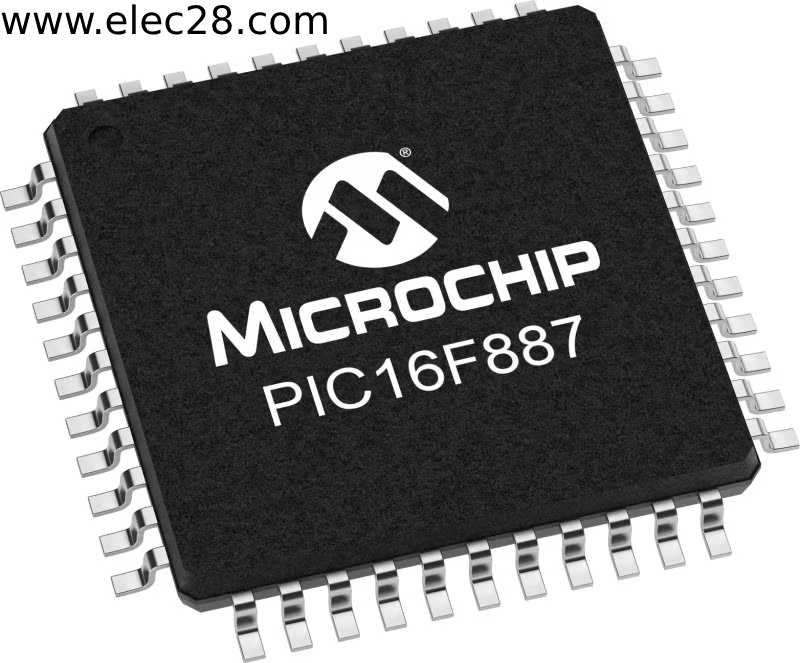
One popular and adaptable part in embedded systems is the PIC16F887 microcontroller. The PIC16F887, with its high- performance RISC CPU, abundant flash memory, and different peripherals, offers a reliable foundation for the creation of inventive results ranging from consumer electronics to motorcars.
II. Getting Started
A. Required hardware and software
First effects first, the hardware and software factors must be assembled before beginning to program the PIC16F887 microcontroller. A PIC16F887 microcontroller chip, a breadboard, a power force, a programmer/ tableware device( similar PICkit or MPLAB ICD), and different electronic factors for testing and prototyping are needed for the hardware. You’ll require the XC8 compiler, the necessary tackle accoutrements , and an intertwined development terrain( IDE), similar as the MPLAB X IDE, for the software. A reliable textbook editor and interpretation control system might also help to speed up the development process.
B. Setting up the development environment
Setting up the development environment is a critical first step in making sure PIC16F887 programming goes easily and effectively. Installing the MPLAB X IDE and XC8 compiler on your computer is the first step; make sure they’re duly set up and up to date. Next, use the MPLAB X IDE or the manufacturer’s software to test the functioning of your programmer/ tableware device by connecting it to the PC. After everything is set up, open the MPLAB X IDE, open a new design, elect PIC16F887 as the target device, and acclimate the design parameters to suit your conditions.
C. Understanding the datasheet
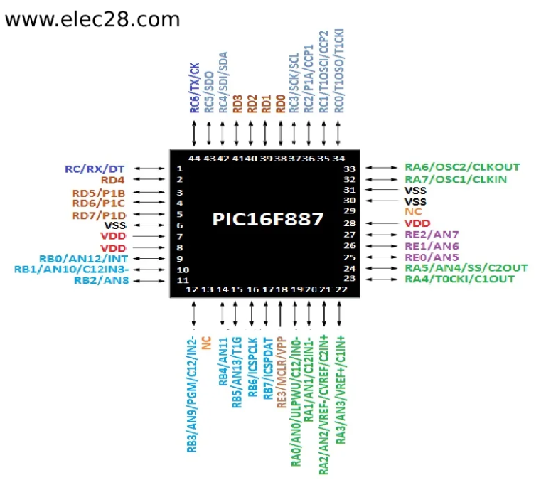
Comprehending the PIC16F887 microcontroller’s data distance is pivotal for effectively programming and exercising its features. The instruction set armature, supplemental module armature, memory operation, electrical parcels, and pinout of the microcontroller are all covered in detail in the datasheet. To make well- informed opinions during the development process, you can gain an understanding of the PIC16F887’s capabilities and limits by precisely examining the datasheet. likewise, the datasheet serves as an inestimable reference tool for register configuration, supplemental function deployment, and programming and tackle interface job troubleshooting.

III. Basic Concepts
A. Introduction to PIC assembly language
The foundation for programming the PIC16F887 microcontroller is an introduction to the PIC compiler language. Assembly language, in contrast to high-level languages, enables direct control over the microcontroller’s hardware resources and instructions.
B. Memory organization
Because memory structure controls how information and instructions are stored and accessible in the microcontroller, it is a crucial component of PIC16F887 programming. Special function registers (SFRs), RAM, and Flash program memory are among the memory types available to the PIC16F887. User program code is kept in program memory, and temporary data and variables are kept in data memory while the program is running. The microcontroller’s peripherals and configuration settings are managed by Special Function Registers (SFRs).
C. Input/output operations
A key component of connecting the PIC16F887 microcontroller to peripherals and sensors is input/output (I/O) activities. Numerous I/O connections on the microcontroller can be set up as digital inputs or outputs, analog inputs, or special purpose interfaces like SPI, I2C, and UART.
IV. Programming Techniques
A. Writing and compiling code
A PIC16F887 microcontroller requires the use of the proper development tools and programming language for writing and compiling code. While assembly language can be used for low-level tasks, C is the standard programming language for PIC microcontrollers. An integrated development environment (IDE), like the MPLAB X IDE, is used by developers to write code. It offers functions including project management, syntax highlighting, and code completion. After the code is written, it needs to be compiled into PIC16F887-friendly machine code. A compiler, like XC8, often handles this step, translating the high-level code into assembly language instructions that the microcontroller can follow.
B. Uploading code to the PIC16F887
Uploading code to the PIC16F887 microcontroller involves the use of a programmer/silver device to transfer compiled code from the computer to the memory of the microcontroller. The programmer/silver connects to the PC via USB and to the PIC16F887 microcontroller via its programming header. Developers use software tools such as the MPLAB X IDE or stand-alone programming software provided by the programmer/silicon manufacturer to initiate the programming process. Once the code has been successfully uploaded, the microcontroller is ready to execute the programmed commands, controlling various aspects of the embedded system behaviour.
C. Debugging and troubleshooting techniques
Debugging techniques are essential for identifying and resolving errors or problems encountered when programming the PIC16F887. Common debugging techniques include the use of breakpoints to stop program execution at certain points, checking the values of variables using clock-windows, and traversing lines of code to identify the source of errors. In addition, developers can use the IDE’s built-in debugging features or external debugging tools to monitor program flow, register values, and external device interactions in real time. Using systematic debugging and debugging techniques, developers can ensure the reliability, stability and functionality of their PIC16F887-based embedded systems.
V. Practical Examples
A. LED blinking
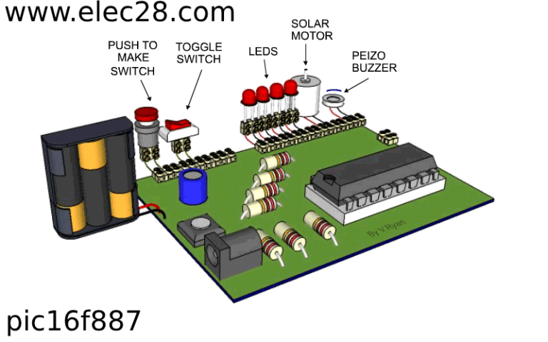
One of the easiest yet most fundamental microcontroller programming activities is to make an LED blink. This is a good way for newcomers to become acquainted with GPIO (general purpose input/output) functions. The LED may be made to flash by setting up a digital output contact and writing code to regularly toggle the pin state. In addition to showing fundamental I/O control, this introductory exercise gives a general overview of the PIC16F887 program structure, covering setup, circuit execution, and delay mechanisms. The flashing LEDs serve as building blocks for more intricate projects and aid in the understanding of programming principles.
B. Sensor interfacing
In order to gather environmental data and react to external stimuli, the PIC16F887 microcontroller is integrated with a variety of sensors using the sensor interface. Motion, humidity, temperature, and other types of sensors are examples of sensors. The sensors’ GPIO pins or analogue input channels can be connected to by developers to read the sensor outputs and process them with the right algorithms. Sensor data can be used to automate control systems, monitor the environment, or set off particular activities based on pre-established thresholds. The sensor interface highlights the PIC16F887’s adaptability for practical data collection and embedded application utilization.
C. Motor control
The PIC16F887 microcontroller’s capacity to control and regulate motors in a variety of electromechanical systems is demonstrated by motor control. The PIC16F887 can produce the necessary control signals to change the speed, direction, and location of a motor, whether it is used to operate servo, stepper, or DC motors. Developers can design precise control algorithms to obtain desired motion profiles by connecting the microcontroller to motor driver circuits or motor controller modules. Applications for motor control range from straightforward ones like drone stabilization and CNC machine control to more intricate ones like robot motion and conveyor belt management, demonstrating the PIC16F887’s adaptability and scalability for managing electromechanical systems.
VI. Conclusion
To sum up, this lesson has given a thorough introduction to programming the PIC16F887 microcontroller, including key ideas, sophisticated functions, real-world applications, and recommended practices. To fully utilize the PIC16F887, developers have learned essential skills such as comprehending the microcontroller’s design and implementing advanced capabilities like motor control, interrupt management, and sensor interfacing. To guarantee project success and sustainability, the guide’s main points—which are underscored throughout—include the significance of efficient code optimization, comprehensive documentation, and version control.

