There will always be some noise in the time and frequency domains when using an oscilloscope to check the stability of your power supply voltage. Your objective as a PCB designer is to locate different sources of noise and take action to minimize them.
Basic actions such as filtering and decoupling capacitors are suitable for specific noise sources, but when working with very rapid digital signals (less than ~1 ns rise time, per Rick Hartley), they will not offer adequate decoupling. Knowing how various noise sources manifest in the frequency and temporal domains aids in the identification of your noise sources as part of PCB design, especially in the analysis of power integrity and signal integrity. Here’s how to identify ripple voltage in your PDN and how it might lead to power integrity issues in your board from ripple voltage sources and other noise sources.
Causes of Ripple Voltage and Power Supply Noise
There are four types of intrinsic noise on your PCB’s power rails and from your power supply:
In the frequency domain, there is random noise. Over the whole frequency range, this noise manifests as thermal noise, also known as Johnson-Nyquist noise. This white noise, or noise that is dispersed throughout the whole frequency spectrum, is Gaussian (that is, variations in temporal magnitude occur according to a Gaussian process).
Changing sounds. This can be seen on the output of a switching regulator (buck-boost converter, flyback/forward converter, VRM, etc.) at particular frequencies. The PWM signal that the converter uses to switch one or more FET drivers is the source of this noise.
Although this kind of oscillation resembles a power conversion ripple, it is not the same. This results from the PDN’s parasitic inductance and capacitance. An IC draws a sudden current when it changes states or output levels, resulting in a brief oscillation that is frequently referred to as a ripple voltage. The power rails may exhibit this transient response even in the case of regulated supply voltage.
It is your responsibility as a designer to predict when each of these various noise sources will be noticeable and to take action to either eliminate or reduce them.
We haven’t talked about the fifth source of noise, but it has to do with the PWM switching noise in a switching regulator, as was previously explained. A switching regulator’s output will include conducted electromagnetic interference (EMI) at frequencies of around kHz, which is capable of readily causing a current to flow through a circuit downstream.
A switching regulator has the ability to introduce noise into a downstream circuit through radiated EMI, even if this EMI is typically eliminated through filtering. The parasitic inductance of downstream circuits is large enough (typically ~nH) in regulators that produce sufficient current (~5 A or more) to induce a sizable voltage spike. This increase may be significant enough to result in accidental switching and raise bit error rates. This will, at the very least, cause a downstream IC’s jitter and phase noise to rise.
Ripple Voltage: Power Rail Ringing or Smoothing Capacitor Ripple?
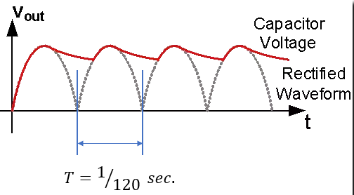
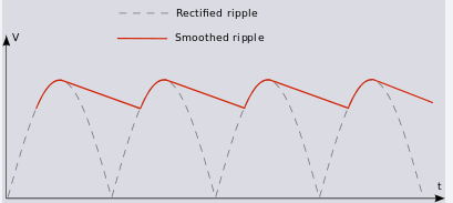
The main distinction between transitory ringing and ripple from a smoothing capacitor is the oscillation’s apparent frequency. When converting a 60 Hz or 50 Hz sinusoidal power supply to its absolute value, a rectifier bridge is utilized for AC-DC conversion. A smoothing capacitor is then employed to convert the absolute value of the signal to a DC signal. There is a ripple in the rectifier’s output at twice the frequency of the input AC signal because the smoothing capacitor in the rectifier bridge discharges twice a cycle. A bandstop filter can lessen the effects of this specific frequency. The output is still unregulated as a result, thus if the load impedance changes, the voltage that the load sees will also change.

Typically, an AC-DC converter’s output—which is essentially an uncontrolled power source—is fed into a regulator, which is typically a switching regulator. A regulator’s purpose is to maintain the output voltage in the face of variations in the output’s load, which frequently occurs when working with nonlinear circuit components (transistors, diodes, etc.). Up to a certain maximum value, the gadget outputs some current while maintaining a steady voltage. A diode and switching a FET driver that is powered by a PWM single offer regulation. This reduces ripple from a rectifier bridge as a result, but it also causes the previously noted switching noise.
A power regulator’s noise is not a low-frequency, smooth oscillation. Rather, it manifests as a frequency-domain high-Q peak, often observed at frequencies of approximately 100 kHz.
Now compare this to a voltage that is transiently rippled. Higher frequencies that match to the PDN’s damped transient oscillation frequency are where the transient ripple voltage manifests itself. Although it could look as a damped oscillation on the PDN, this usually manifests as an underdamped oscillation during a single switching event. Another way to see this would be as a forced oscillation, such in the signal trace below.
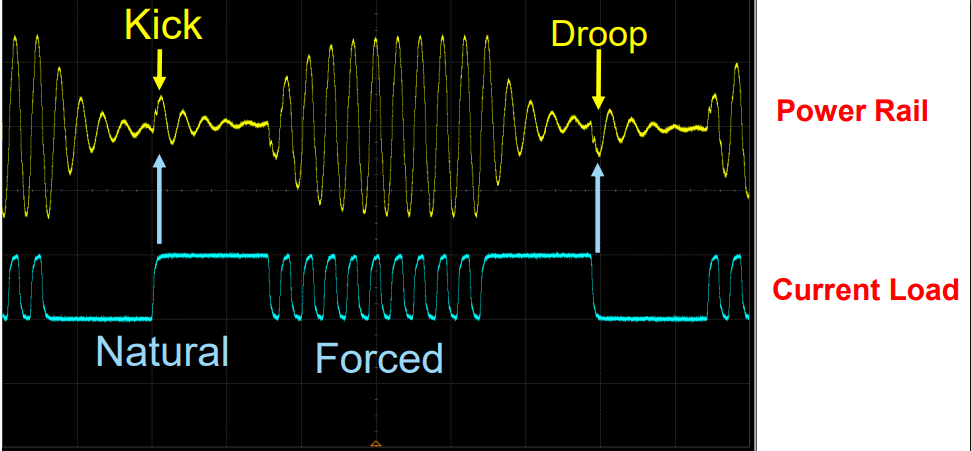
The propagation of a transient ripple voltage across a system is depicted in Fig. 3 below. In order to account for parasitics, you will need to use a post-layout tool to mimic the behavior of your PDN design during the schematic and PCB design phases. In order to guarantee that the ripple voltage in your integrated circuits is smaller than the noise margin, the PDN impedance must be kept below a certain target value.


