I. Introduction
A. Definition of GND (Ground) in electronics
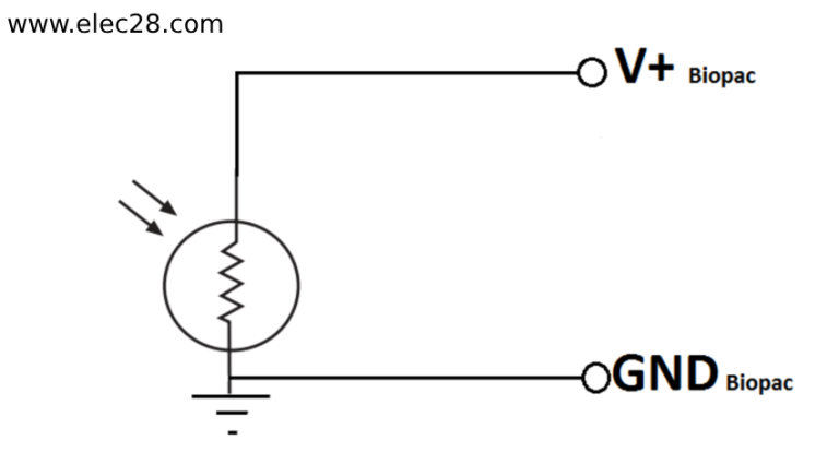
In the realm of electronics, GND, or ground, serves as the reference point for voltage levels within a circuit. It’s often represented by a horizontal line with three downward-pointing arrows. GND is typically connected to the negative terminal of a power supply or the earth in practical applications.
B. Importance of GND in electrical circuits
Understanding the concept of GND is fundamental in electrical circuits as it establishes a common voltage reference point, ensuring stable and predictable operation. Without GND, circuits would lack a stable reference point, leading to unpredictable behavior and potential damage to electronic components. Hence, comprehending GND is crucial for designing and troubleshooting electronic systems.
II. Functions of GND
A. Reference point for voltage measurements
GND serves as a reference point for voltage measurements within a circuit. Engineers can precisely ascertain potential differences between various locations in the circuit by measuring all voltages with respect to this reference point. By doing this, the circuit’s various components and sections are guaranteed to have stable and dependable voltage levels.
B. Providing a return path for current
Another critical function of GND is to provide a return path for electric current. Current travels through the components in an electrical circuit before returning to the power source. By enabling uninterrupted current flow back to the power source or supply, the GND completes the circuit and aids in this return path.
C. Stabilizing circuit operation
Additionally, GND helps stabilize circuit operation by ensuring that excess charge is safely dissipated. By acting as a switch for any extra charge in the circuit, it guards against voltage swings or surges that can harm internal parts. This stabilization contributes to the longevity and dependability of electronic equipment by ensuring that it operates as intended. It is imperative to comprehend these functionalities in order to build and debug circuits effectively.

III. Types of Grounds
A. Signal Ground
Signal grounding serves as a common reference point for the signal voltages inside a circuit. It is also sometimes referred to as analogue grounding or reference grounding. It offers a low impedance channel for signal return paths, enabling steady and precise signal processing. Separating the analogue and digital planes in mixed-signal systems improves circuit performance and lowers electromagnetic interference (EMI) by preventing noise coupling and signal distortion.
B. Earth Ground
Electrical systems and equipment are connected to a ground conducting surface via a ground, commonly referred to as a protective ground or safety ground. In the case of an electrical fault or short circuit, it enables fault currents to safely dissipate into the ground, reducing the possibility of electric shock and guaranteeing operator safety. Adherence to safety regulations for electrical installations and preservation of equipment integrity necessitate the use of appropriate bonding and grounding techniques.
C. Chassis Ground
A metal chassis or electrical equipment enclosure must be earthed. This process is known as chassis earthing, sometimes known as frame earthing or equipment earthing. It serves as a benchmark for EMI suppression and shielding, lowering electromagnetic interference and guaranteeing adherence to electromagnetic compatibility (EMC) regulations. Additionally, chassis grounding permits fault currents and aids in the dissipation of static charges, enhancing the dependability and security of equipment in automotive and industrial settings.

IV. GND Symbols and Representations
A. Electrical symbols for GND
Electrical symbols for GND vary depending on the standards and conventions followed in circuit diagrams. The most widely used ground symbol is a horizontal line that resembles the Earth to Earth symbol and has three arrows pointing downward. The letters “GND” or “AGND” (analog ground) or “DGND” (digital ground) may be used to represent GND on various diagrams. These symbols help identify the reference point for voltage measurements and current paths within a circuit, ensuring proper grounding for electrical systems.
B. Common representations in circuit diagrams
In circuit diagrams, GND is typically represented by a node or connection point where ground connections are made. This may be denoted by a triangular symbol with one side connected to the ground reference. Alternatively, GND may be indicated by a horizontal line intersecting multiple circuit components, serving as a common ground reference for the entire system. These representations help simplify circuit diagrams and ensure clarity in understanding the grounding scheme of electronic circuits.

V. Practical Considerations
A. Proper grounding techniques
Proper grounding techniques are essential to ensure the stability and reliability of electronic circuits. Ground connections should be made using thick conductors with low resistance to minimize voltage drops and ensure a robust ground connection. Additionally, ground connections should be made at multiple points within the circuit to prevent ground loops and ensure uniform grounding across all components.
B. Avoiding ground loops and noise
Ground loops occur when there are multiple paths for current flow between different ground points in a circuit, leading to unwanted noise and interference. To avoid ground loops, it’s crucial to design circuits with a single-point ground reference and to minimize the loop area between ground connections. Grounding techniques such as star grounding and using twisted pair cables can help reduce the risk of ground loops and associated noise.
C. GND isolation in sensitive circuits
In sensitive circuits such as analog and high-frequency circuits, GND isolation may be necessary to prevent interference and maintain signal integrity. Isolating the ground of sensitive components from the main ground plane can help reduce noise and improve the performance of the circuit. Techniques such as ground plane partitioning, using ground isolation transformers, and implementing differential signaling can help achieve effective GND isolation in sensitive circuits.
VI. Importance of GND in Different Applications
A. Audio circuits
The GND signal voltage serves as a crucial reference point for audio signals, preserving signal integrity and reducing noise. In order to prevent ground loops and other interference that can lower sound quality, proper grounding techniques are crucial in audio applications. By maintaining a low noise environment, grounding techniques like star grounding and the use of specialized ground planes help to ensure precise and clear sound reproduction.
B. Power supply circuits
GND is essential to power supply circuits because it guarantees current return and stabilizes voltage levels. Strong and low impedance power supply ground connections are necessary to reduce voltage drop and guarantee effective power distribution. Furthermore, adequate grounding guarantees the stability and dependability of power supply outputs while reducing normal mode noise.
C. High-frequency circuits
Grounding and grounding (GND) is essential in high-frequency circuits, like RF and microwave systems, in order to preserve signal integrity and lower electromagnetic interference (EMI). In order to minimize parasitic capacitance and inductance, high frequency circuit grounding solutions should concentrate on minimizing ground loops and optimizing ground plane placement. In sensitive circuits, GND helps preserve signal integrity and guards against signal degradation by giving high frequency currents a low impedance channel.
VII. Conclusion
In electronics, ground (GND) is crucial because it serves as a reference point for measuring voltage, a conduit for current to return, and a means of stabilizing circuit functioning. It is crucial for maintaining correct operation, reliability, and signal integrity in a variety of electronic systems and gadgets. It is essential to emphasize correct grounding techniques in order to prevent issues like signal deterioration, noise interference, and ground loops. To maintain low noise environments and achieve optimal performance of electronic circuits, techniques including GND isolation, star grounding, and ground placement optimization are crucial.
Final Thoughts
Future developments in grounding technology are probably going to concentrate on more sophisticated grounding methods, such as advanced noise reduction, advanced EMI shielding, and active grounding methods. Innovative grounding techniques will remain essential to attaining high performance, dependable, and noise-free operation as electronic systems grow more sensitive and sophisticated.


