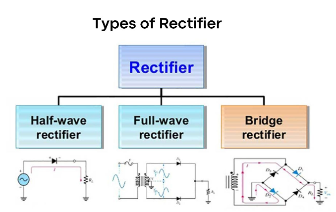
The primary function of a rectifier is to transform AC (alternating current) into DC (direct current) using semiconductor diodes. Rectifiers come in various types, including half-wave, full-wave, and full-wave bridges. Before exploring its applications, it’s essential to revisit the rectifier’s definition.
What is a Rectifier?
A rectifier serves as an electrical component that converts alternating current (AC) into direct current (DC). Analogous to a one-way valve, it permits the flow of electrical current in only one direction. This process of converting AC to DC is termed rectification. Rectifiers can manifest in different physical forms, ranging from solid-state diodes, vacuum tube diodes, mercury-arc valves, silicon-controlled rectifiers, to various other silicon-based semiconductor switches. Now that we’ve elucidated the rectifier’s definition, let’s delve into some of its applications.
Working of Bridge Rectifier Circuit
The circuit diagram illustrates a specific connection pattern of diodes, defining the unique configuration that lends its name to the converter. In a bridge rectifier, the input voltage can originate from various sources, including transformers for stepping up or down voltage or from the domestic power supply mains. For this discussion, a 6-0-6 center-tapped transformer is utilized to supply AC voltage.
During the initial phase of the rectifier’s operation, in the positive half cycle, diodes D3-D2 become forward biased and conduct electricity. Simultaneously, D1-D4 are reversed biased, remaining non-conductive and acting as open switches. Consequently, a positive half cycle emerges at the output. Conversely, in the negative half cycle, D1-D4 become forward biased and conduct current, while D3-D2 are reversed biased, remaining non-conductive in this phase.
Types of Inductors and Their Applications
Once more, a positive half cycle emerges at the output, culminating the rectification process that converts the negative part of the AC current into a positive cycle. The rectifier’s output comprises two half-positive pulses, mirroring the input’s frequency and magnitude.
In contrast to the half-wave rectifier’s functionality, the full bridge rectifier features an additional branch that enables conduction during the negative half of the voltage waveform, a capability absent in the half-bridge rectifier. As a result, the average output voltage of the full bridge rectifier doubles that of its half-bridge counterpart.
While constructing a full-wave bridge rectifier typically involves utilizing four individual power diodes, ready-made bridge rectifier components are conveniently available in various voltage and current specifications. These pre-made components can be directly employed to create a functioning circuit.
Post-rectification, the output voltage waveform doesn’t constitute a pure DC signal. To refine it into a more direct current waveform, a capacitor is utilized for filtering purposes. Smoothing or reservoir capacitors, connected in parallel with the load across the output of the full wave bridge rectifier circuit, elevate the average DC output level to the desired average DC voltage. The capacitor acts not only as a filtering component but also charges and discharges intermittently, effectively augmenting the output voltage.
The capacitor charges as the waveform reaches its peak and uniformly discharges into the load circuit as the waveform descends. This ensures a steady voltage supply to the load circuit, thereby establishing the DC output as the waveform diminishes.
Advantages of a Bridge Rectifier:
Minimized ripples in the output DC signal
High rectifier efficiency
Reduced power loss
Disadvantages of Bridge Rectifier:
Higher complexity compared to a half-wave rectifier
Increased power loss in comparison to a center-tapped full-wave rectifier
Here’s a compilation of common applications and uses of various Rectifiers:
Rectification, i.e., converting DC Voltages to AC Voltages
Electric welding for providing polarized voltage
Implementation in traction, rolling stock, and three-phase traction motors for train operations
Usage in mosquito repellents and soldering irons employing half-wave rectifiers
AM Radio utilization for detection and signal peak detection using half-wave rectifiers
Application in modulation, demodulation, and voltage multipliers
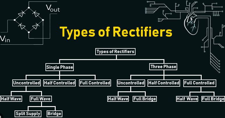
Rectifiers can be classified into Single Phase and Three Phase categories based on the input they operate on. When the input is single phase, it’s termed as a single-phase rectifier, while three-phase rectifiers handle three-phase inputs.
A single-phase bridge rectifier consists of four diodes, while a three-phase rectifier utilizes six diodes arranged in a specific configuration to achieve the desired output. These rectifiers can be controlled or uncontrolled, contingent on the switching components employed, such as diodes, Thyristors, etc.
A rectifier is used for powering appliances
As is widely understood, nearly all electrical devices rely on a DC power supply for their operation. The integration of a rectifier within the power system serves the crucial function of converting AC to DC power. Particularly, bridge rectifiers find extensive use in larger appliances, adept at transforming high AC voltages into lower DC voltages.
Rectifiers are frequently employed in conjunction with transformers. Utilizing a half-wave rectifier alongside step-down or step-up transformers allows for the attainment of desired DC voltage levels. Full-wave rectifiers, on the other hand, power motors and LEDs functioning on DC voltage.
In diverse applications, rectifiers play pivotal roles. They feature prominently in soldering iron circuits and mosquito repellents to drive fumes, employing half-wave rectifiers. Moreover, bridge rectifier circuits are pivotal in electric welding, providing stable and polarized DC voltage.
AM radios utilize half-wave rectifiers as detectors due to their output containing an audio signal. Despite their lower current intensity, these rectifiers hold lesser relevance in more intricate systems.
In various circuit applications, half-wave rectifiers are integral components in firing circuits and pulse generators. Their role extends to modulation, where they demodulate the amplitude of a modulated signal. Conversely, full-wave bridge rectifiers are employed in radio signals to detect modulating signal amplitudes.
For voltage multiplication purposes, half-wave rectifiers are employed to realize voltage multiplication circuits.
This compilation highlights some applications of rectifiers. For further insights, consider exploring additional information available on BYJU’s Learning App.
Frequently Asked Questions – FAQs
Q1: What defines a rectifier?
A rectifier encompasses one or more diodes utilized for converting AC into DC.
Q2: List three advantages of a bridge rectifier.
Here are three advantages of a bridge rectifier:
Doubled rectification efficiency compared to a half-wave rectifier.
Employing a straightforward filtering circuit due to minimal ripple voltage in bridge rectifiers.
High Transformer Utilization Factor (TUF).
Q3: What serves as an alternative to a bridge rectifier?
A full-wave rectifier stands as an alternative to the bridge rectifier.
Q4: Identify three fundamental types of rectifiers?
The three primary rectifier types include half-wave rectifiers, full-wave center-tapped rectifiers, and full-wave bridge rectifiers.
Q5: How is the efficiency of a rectifier measured?
Rectifier efficiency is gauged by the ratio of DC output power to the applied AC input power.


